


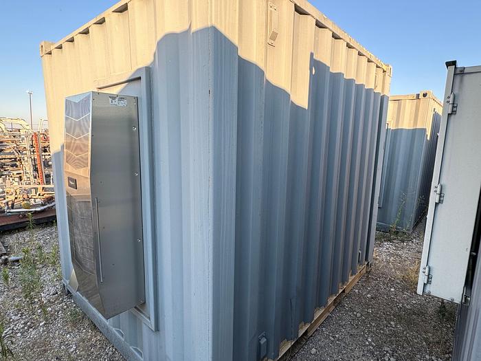
Enclosed Command Center For LNG Station - Controls for any project site
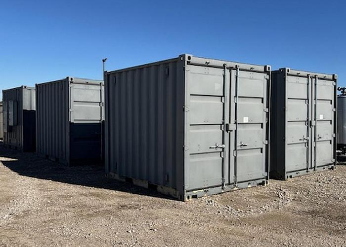
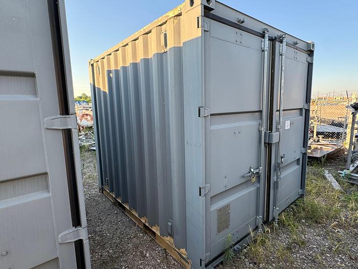
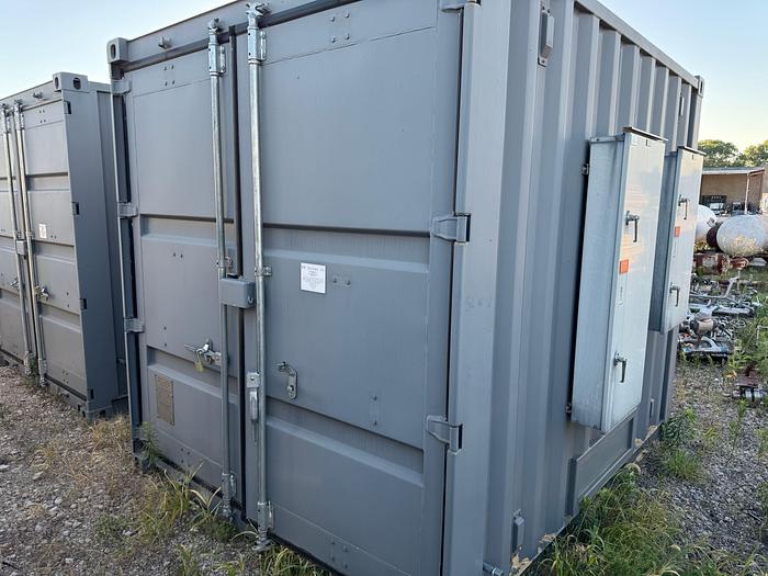
Enclosed Command Center For LNG Station - Controls for any project site
Available quantity:13
Description
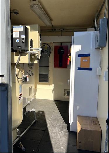
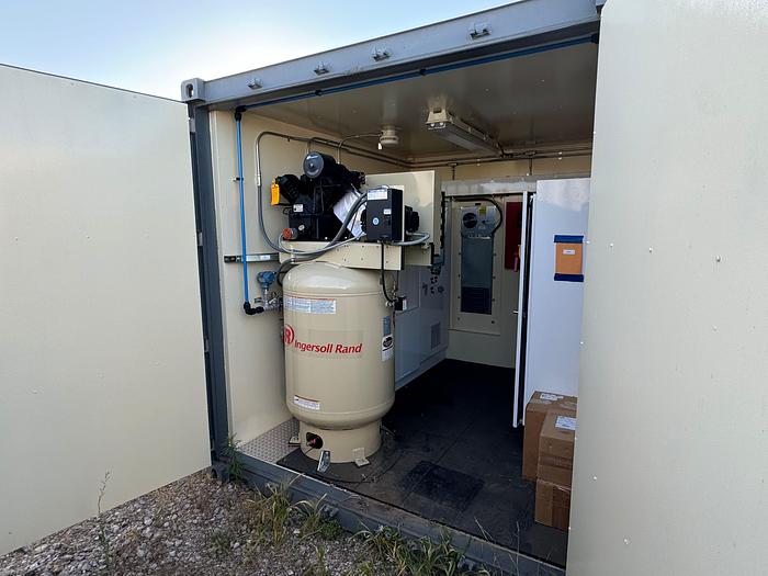
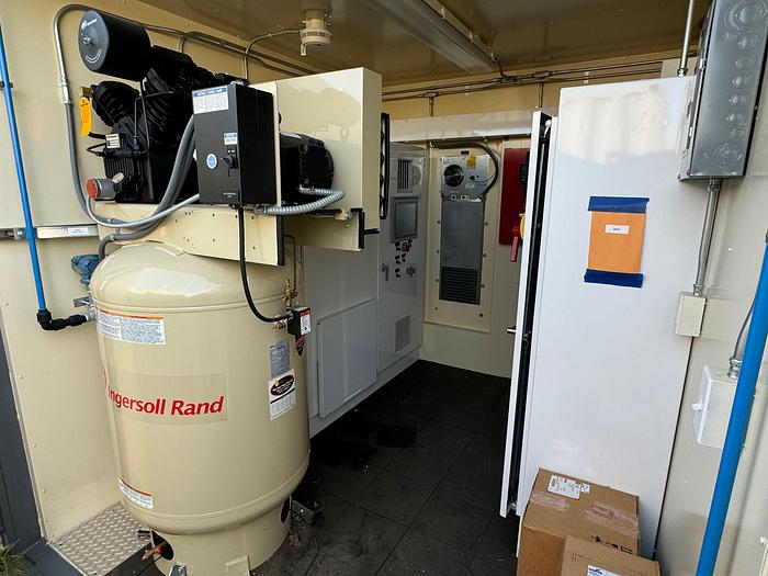
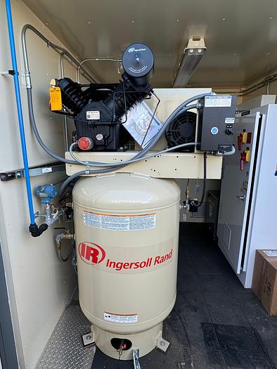
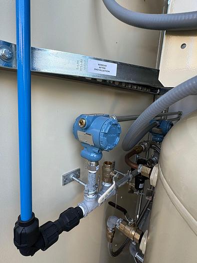
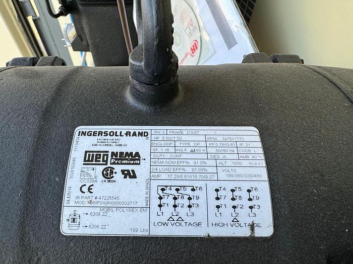
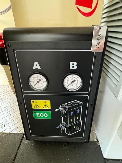
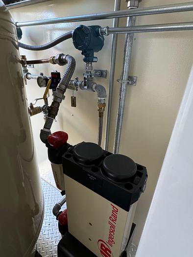
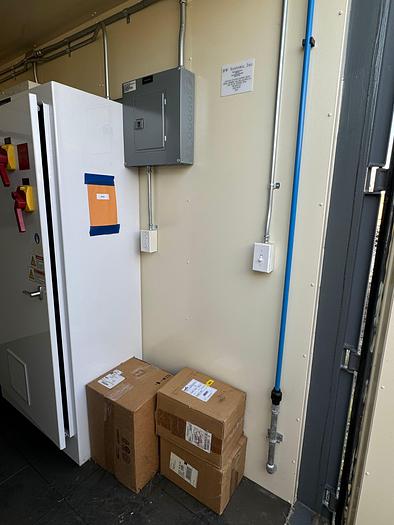
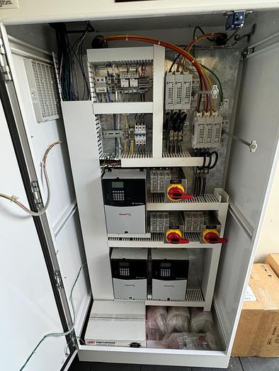
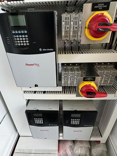
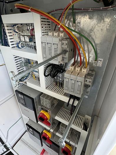
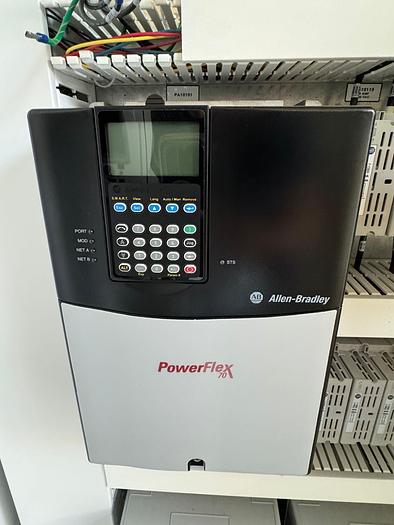
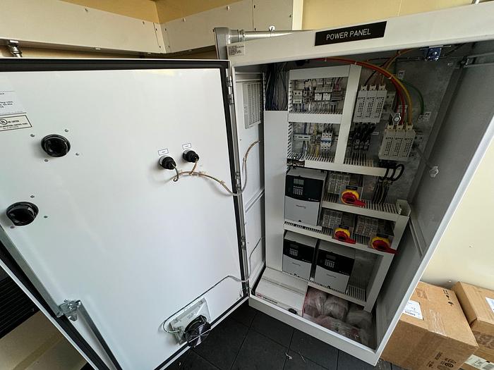
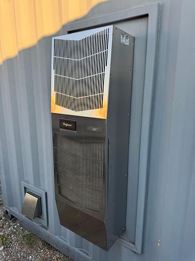
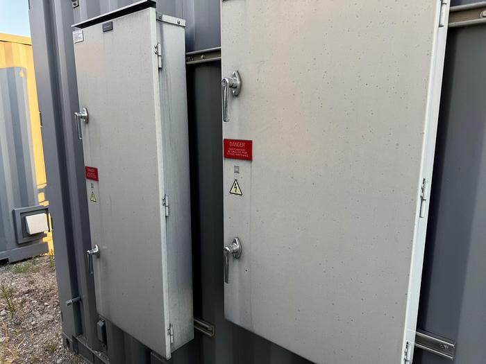
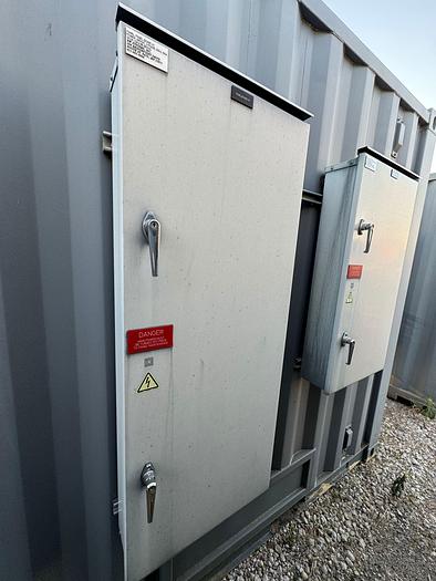
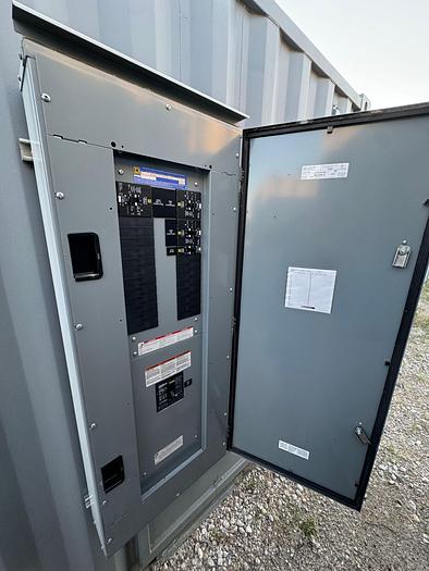
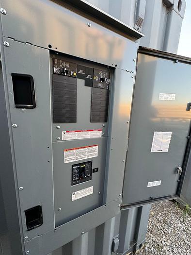
You are looking at the state of the art control, control center 10x10 container that can be used for operating any small plant set up. With all of the hardware included in those containers you can incorporate any logic that you see fit for your project. Please carefully review all of the high-quality components for functionality those control centers offer. They were designed to operate stand alone LNG public stations for one of the major US energy company and no expense were spared for reliability, safety and functionality. Best in class components were used and redundancies on multiple levels were implemented into the set up. Look at the components and you will be amazed how much operations one of those containers can control.
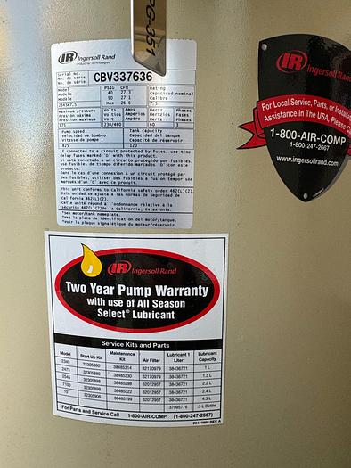
We have all of the schematics for the control centers and all of the main components.
Below more details for your review:
Specifications
Storage Tank V-101
Inner Tank
- Gross Water Volume- 18,000 Gallons
- Dimensions- 113.6 in. I.D. x 411 in.
- Construction Material- SA240 T304
- MAWP- 175 psig at the top of the vessel
- MDMT- -320 °F
- Maximum Design Temperature- 120 °F
Outer Jacket
- Dimensions- 134 in. O.D. x 446.9 in.
- Construction Material- A36
- Design Pressure- -15 psig
- Minimum Design Temperature- -40 °F
- Maximum Design Temperature- 150 °F
Nitrogen Pressure Vessel V-301
Inner Tank
- Gross Water Volume- 3,150 gal.
- Dimensions- 72.5 in. I.D. x 179.3 in.
- Construction Material- SA240 T304
- Design Pressure- 250 psig
- MDMT- -320 °F
- Maximum Design Temperature- 120 °F
Outer Tank
- Dimensions- 86 in. O.D. x 205.1 in.
- Construction Material- A36 Carbon
- Minimum Design Temperature- -40 °F
- Maximum Design Temperature- 150 °F
- Maximum Design Pressure- -15 psig
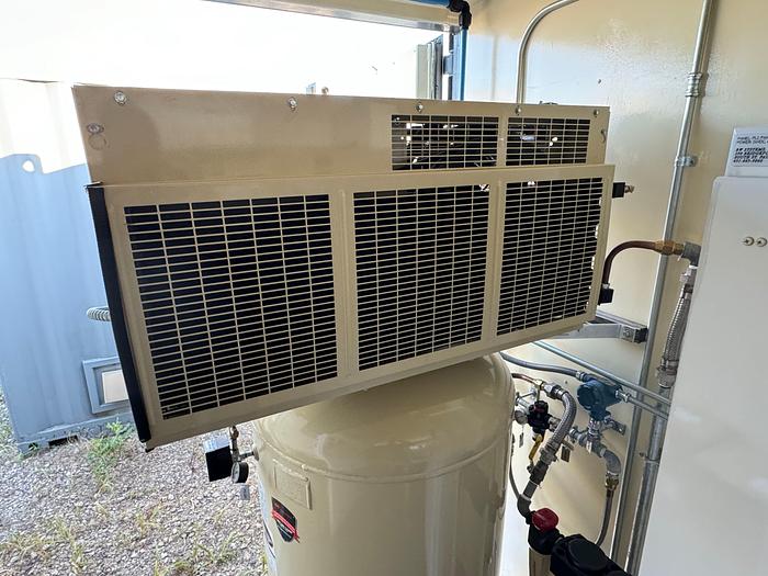
Saturation Vaporizer VAP-501
- Dimensions- 240 Linear Feet
- Construction Material- Unlined Aluminum Fin
- MDMT- -320 °F
- Maximum Design Temperature- 150 °F
- Maximum Design Pressure- 450 psig
- Minimum Design Pressure- 0 psig
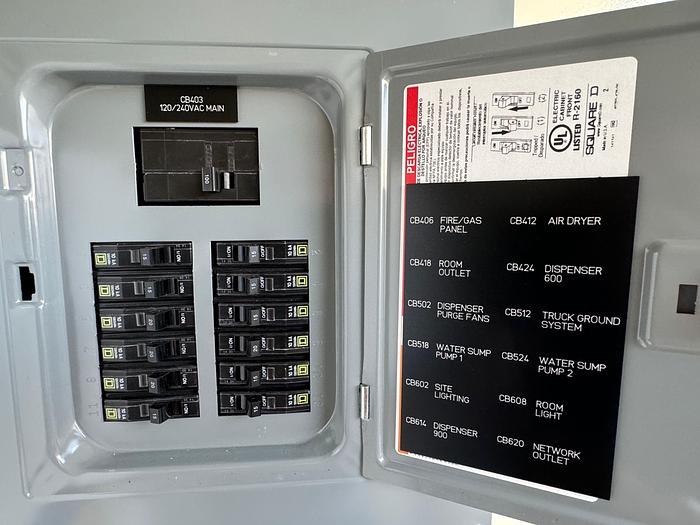
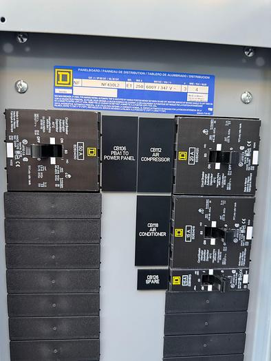
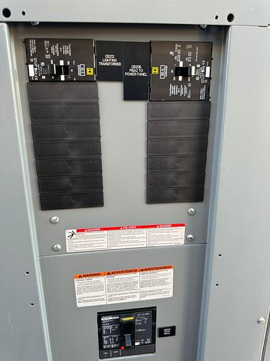
Station Control System
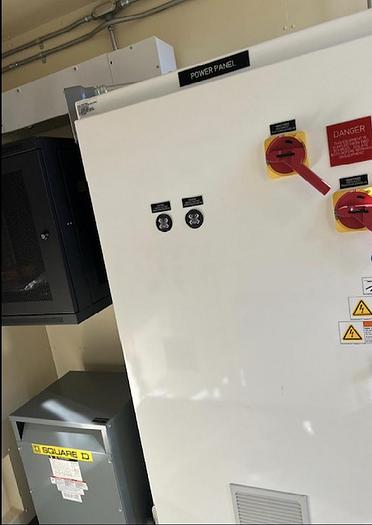
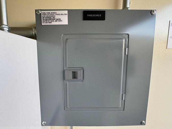
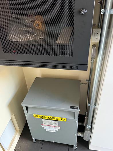
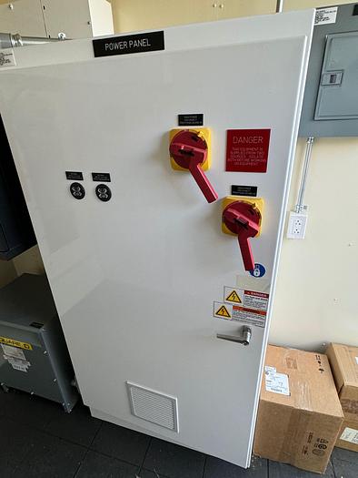
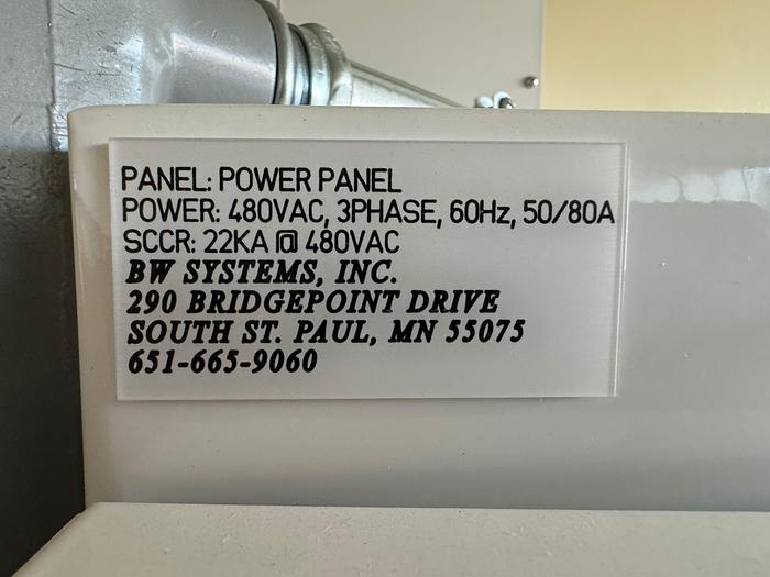
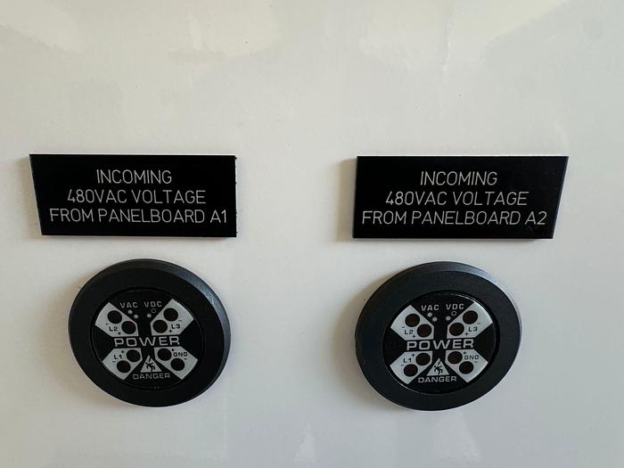
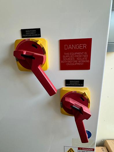
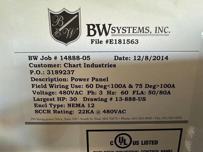
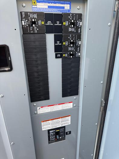
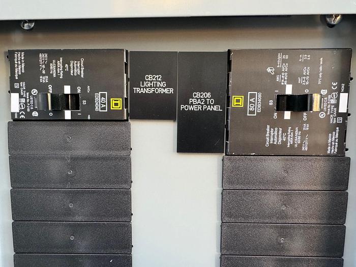
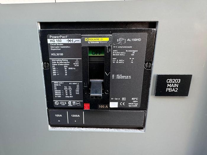
CP1 Power Panel
The CP1 Power Panel is located in the control room. The controls and
indicators on CP1 function as follows:
- MAIN POWER DISCONNECT FROM PANEL BOARD A1 – electrical
disconnect switch; controls the 480VAC power from panel board A1 to
CP1.
- INCOMING 480VAC VOLTAGE FROM PANEL BOARD A1 – indicator light;
lights when the 480VAC power is switched on from panel board A1 to
CP1.
- MAIN POWER DISCONNECT FROM PANEL BOARD A2 – electrical
disconnect switch; controls the 480VAC power from panel board A2 to
CP1.
- INCOMING 480VAC VOLTAGE FROM PANEL BOARD A2 – indicator light;
lights when the 480VAC power is switched on from panel board A2 to
CP1.
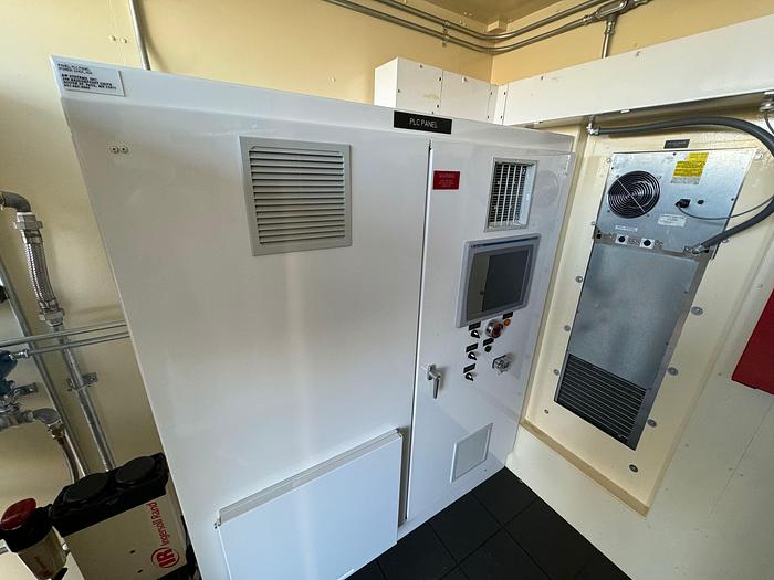
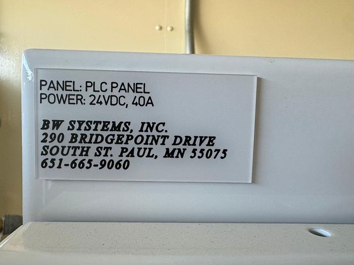
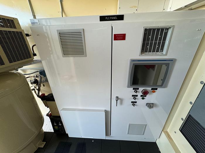
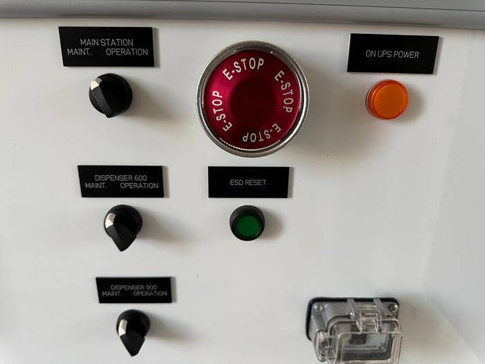
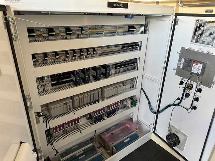
CP2 PLC Panel
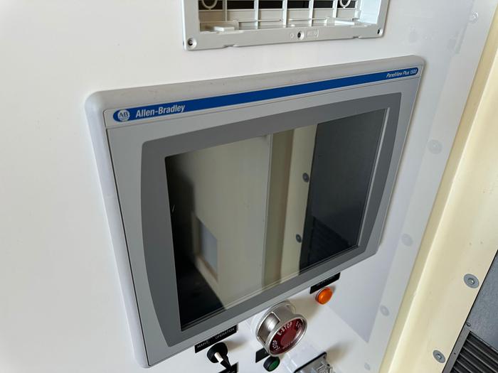
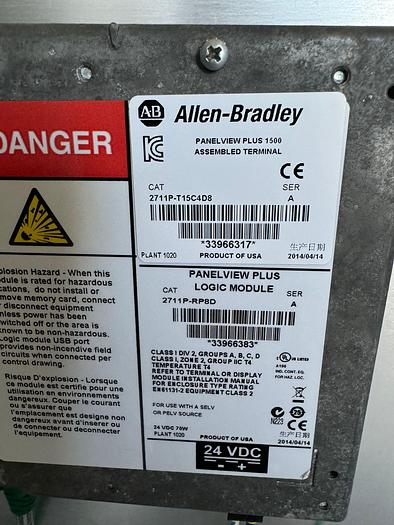
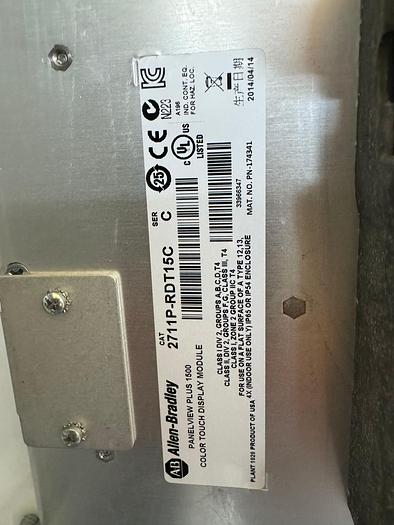
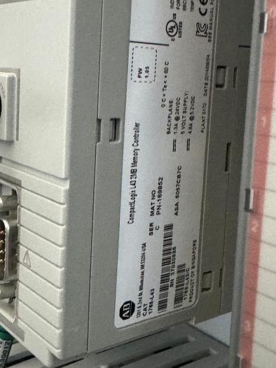
- Allen-Bradley PanelView™ Plus 1500 – Operator Interface (HMI) with touch-screen; displays the screens that allow the Operator view the status of the system and system components. (Refer to the PanelView HMI Screens subsection for screen functions.)
- MAIN STATION / MAINT. / OPERATION – two-position selector switch; selects the system maintenance or operation mode.
- DISPENSER 600 / MAINT. / OPERATION – two-position selector switch; selects the Dispenser 600 maintenance or operation mode.
- DISPENSER 900 / MAINT. / OPERATION – two-position selector switch; selects the Dispenser 900 maintenance or operation mode.
- ESD (Emergency Shutdown) – palm switch; generates an emergency shutdown.
- ESD RESET – black push button; resets the safety circuit when pressed.
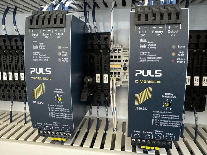
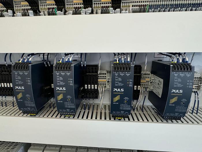
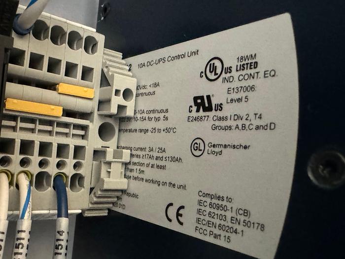
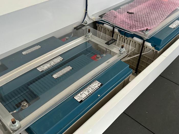
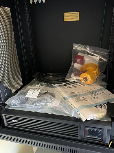
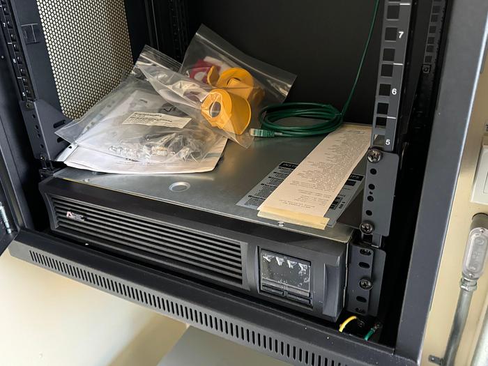
- ON UPS POWER – amber indicator light; switches on when the system has lost utility power and is running on the Uninterruptible Power Supply.
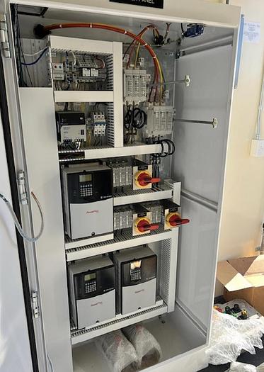
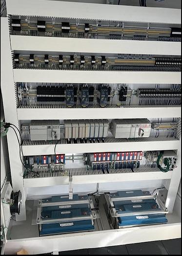
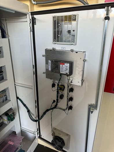
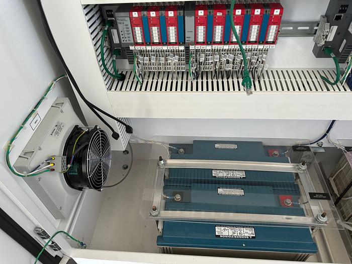
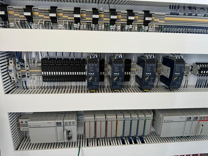
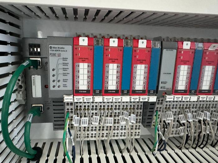
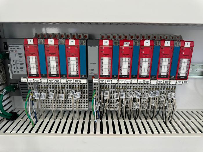
The station control system consists of the following:
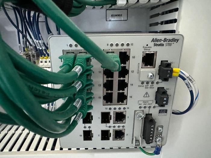
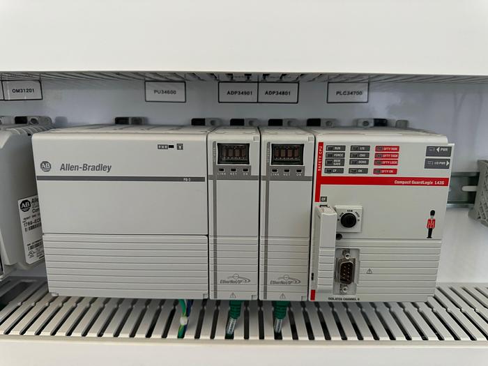
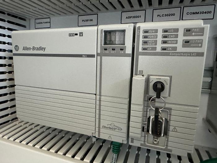
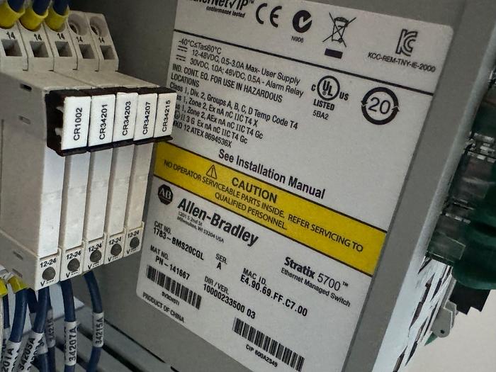
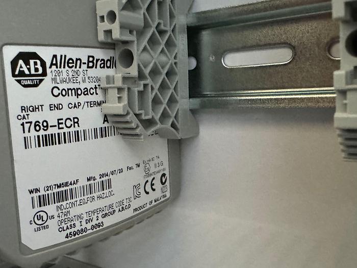
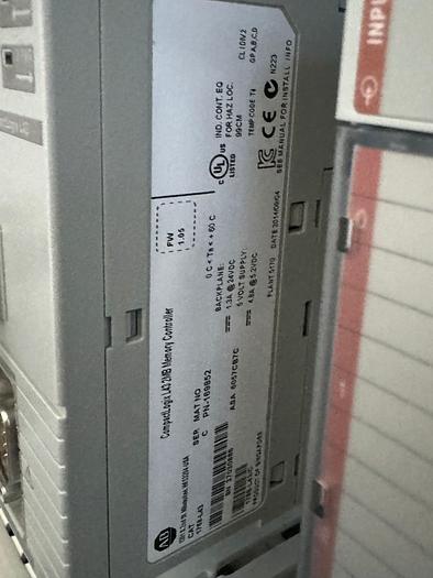
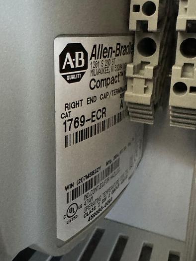
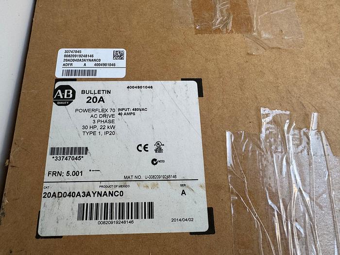
- Two segregated Allen-Bradley PLCs.
(The control PLC controls the pumps, air-actuated valves (AVs), and system logic. The PLC also monitors the non-safety system temperatures, pressures, liquid levels, and interlocks.)
(The safety PLC is segregated from the control PLC. The fire and gas detection functions, Emergency Shut Down (ESD) buttons, and the shutdown-related system temperatures pressures, and liquid levels are integrated into the safety PLC.) The control and safety PLCs communicate with each other via an integrated control bus. The bus is only used for control.
- Relays to implement shutdowns (e.g., ESD buttons).
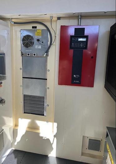
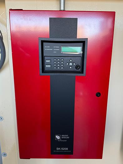
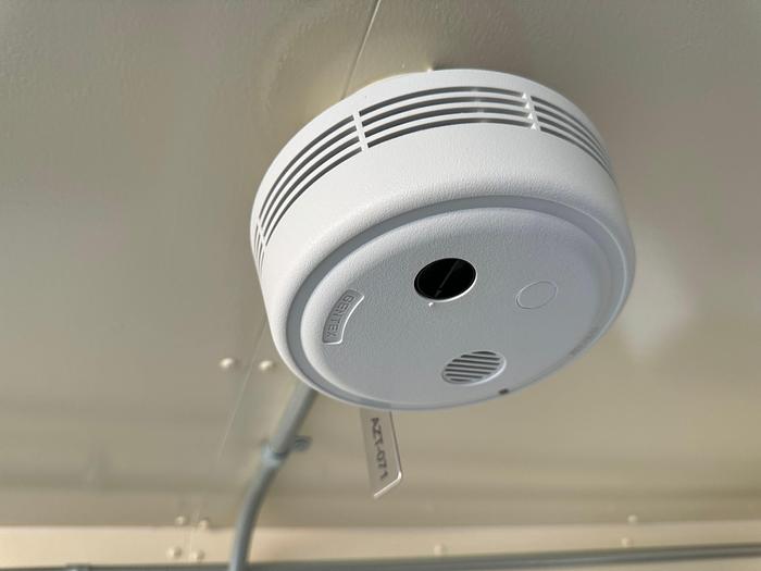
A Honeywell Silent Knight Model 5208 fire alarm control panel with a digital communicator that monitors the station for hazardous conditions related to fire or the presence of flammable gas
Trailer Off-Load Interlock System
- A safety interlock system serves as an interface between the station ESD system and the trailer off-load control unit. This system is based on an electrical cable link between the station and the trailer.
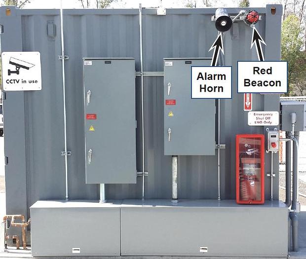
Alarm/Event Annunciation
- The station is equipped with a flashing Red Beacon (YZL-001) and an Alarm Horn (YZH-001)
Data Logging
The PLC time-stamps and logs all alarms and operational events. Other events (e.g., tank inventory), as listed in the Data Logging List, are also recorded.
Pre-purchase inspections are welcomed during normal business hours upon appointment scheduled in advance. We would be happy to provide a complimentary transportation pick up from DFW Airport and back if you want to fly in and see/send someone to inspect the item in person. In addition, we can do Facetime/teams / Zoom calls to go over the skid in person for any domestic /international procurement. Please keep in mind that we are in Dallas and therefore are on the US Central Time (CT) for any communication arrangements.
Shipping Arrangements: The unit is currently located in our yard South of Dallas, Texas. We can assist with shipping arrangements and when properly scheduled, we will provide loading service at no additional charge.
Payment: Payment in full FOB for our yard in South Dallas is required for equipment procurement. We prefer meeting people buying our equipment in person to discuss all aspects of the project requirements and ensure adequate sales support to set your project up for success. We will require a verifiable Cashier check as a payment if you are planning to come in person. We will require a wire transfer in full with the transaction cleared the company account before releasing the equipment to any 3-rd party shipper companies. We are here to help and make this transaction as simple as possible, but we will take all necessary measures to protect us and you.
Please feel free to call/contact Gas Equipment 4 Sale with any questions; we will be happy to answer your online inquiries and/or jump on the call to see how any of our available Gas Equipment 4 Sale can help you meet your project needs.
Specifications
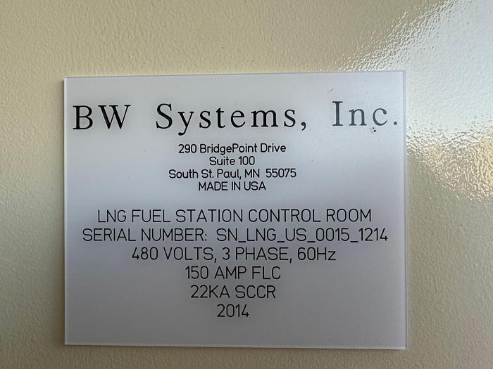
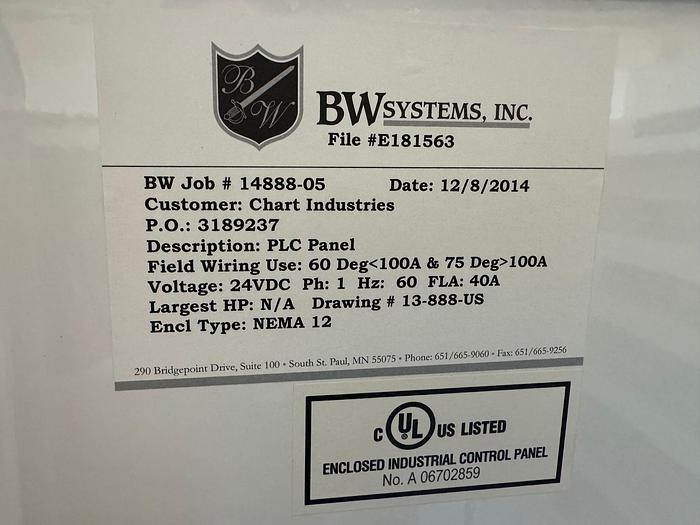
| Manufacturer | BW Systems |
| Year | 2014 |
| Condition | New |
| Stock Number | 0092-CCH-Wax |